
categorias
Electrode Level Sensor — Working Principle, Wiring & Applications | Focusensing
January 31 , 2024Updated November 4, 2026. Reviewed by the Focusens Engineering Team.
| Electrode level sensor | Typical figure |
|---|---|
| Electrode voltage | 4 V AC (Finder 72.01) to 24 V AC (Crouzet LN) |
| Electrode current | 0.2 mA (Finder) to 2 mA (ABB CM-ENS.2x) |
| Sensitivity setting | 0.1 to 1000 kΩ on the relays in section 8 (Gems' 16HM reaches 5.5 MΩ); 6 to 8 kΩ for water (Lovato) |
| Minimum liquid conductivity | about 7.5 to 100 µS/cm, depending on model |
| Electrode cable | 20 to 1000 m on the data sheets; about 5 to 10 m where a 1 nF limit applies, on cable of 100 to 200 pF/m (section 8) |
| Output | Relay, transistor (PNP) or NAMUR (IEC 60947-5-6) signal: point level only |
Sources: the relay data sheets compared in section 8 below; conductivity minimums from VEGA EL 3 (7.5 µS/cm) and E+H TI00375F (10 µS/cm). The full liquid table is in our conductive vs float switch guide linked below.
Electrode level sensors use metal probes (electrodes) that are in the liquid. When the liquid connects the electrodes, a small electrical circuit forms. The electrodes and their holder are usually sold as a conductive level probe and the relay separately; Lovato lists its electrodes as "separately purchased" (Lovato LVM20). The level relay, usually mounted in the panel (some probes carry the electronics in the head, such as E+H's Liquipoint T), compares the resistance of that circuit with its sensitivity setting and switches a contact or a transistor when the liquid reaches an electrode and again when it leaves.
An electrode level sensor is a point-level device. It answers "is liquid at this electrode or not", one height per electrode, and the switching height is set by where each electrode ends. VEGA puts it simply: "The switching signal is determined by the length or mounting position of the respective measuring electrode" (VEGA conductive product information). A water level electrode set therefore gives alarms or pump control at fixed heights, not a continuous level reading.
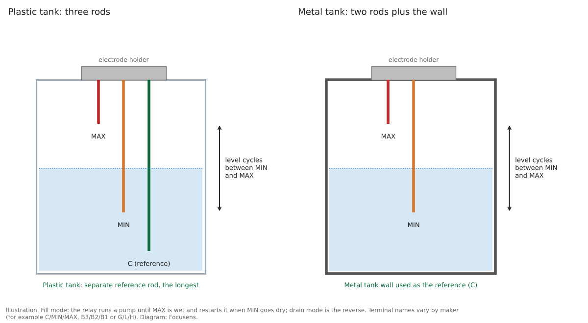
Finder describes the measurement directly: its level relays "work by measuring the resistance through the liquid, between the common (B3) electrode and Min. and Max. electrodes (B2 and B1). If the tank is metalic, then this can be substituted as the B3 electrode" (Finder 72 series).
An electrode level relay wired with two electrodes gives one switching point; wired with three, it gives two-point fill or drain control with a dead band between MIN and MAX. The reference electrode is common to both and is the longest rod, or the tank wall.
| Maker and model | Reference (common) | Lower level | Upper level |
|---|---|---|---|
| ABB CM-ENS | C | MIN | MAX |
| Finder 72 series | B3 | B2 | B1 |
| Eaton EMR6-N | B1 ("earth reference") | B3 | B2 |
| Gems Warrick 16M | G | L | H |
From the ABB CM-ENS.2x, Finder 72 series, Eaton EMR6-N (distributor copy) and Gems Series 16 data sheets. Check the terminal names on your own relay.
ABB's data sheet sets out the two modes for three electrodes: in fill, "the output relay is energized until the MAX-electrode becomes wet. Then it is de-energized and not re-energized until the MIN-electrode becomes dry"; in drain, it "energizes as soon as the MAX-electrode becomes wet" and "remains energized until the liquid level has dropped below the MIN-electrode". For a single level, "only the MAX-electrode shall be connected". Endress+Hauser describes the same difference from the other side: with point level detection the device "switches back as soon as the liquid clears the MIN probe", while with two-point control it "does not switch back until the MAX and MIN probe is cleared" (E+H Liquipoint T).
The tank wall can replace the reference rod in a metal tank. VEGA: "In conductive vessels, the vessel wall can be used as the ground electrode." In a plastic tank it cannot: VEGA advises probes "with a ground electrode in non-conductive vessels, e.g. plastic tanks", and Carlo Gavazzi says the reference must go to the container or, if it is non-conductive, "to an additional electrode" (Carlo Gavazzi CLD1EA1CM24). A metal wall that scales up inside stops conducting well, so Gems recommends a separate ground probe where possible (Gems under-sensing troubleshooting). Check the relay before using the wall: Finder's 24 V DC types must not have any electrode grounded when they run from a grounded supply, and Gems says its reference terminal "should only be connected to the reference probe (or tank) and should not be connected to a panel or electrical ground" (Gems under-sensing troubleshooting).
All three are switching outputs. The electrode relays and probes covered here do not produce a continuous 4–20 mA or 0–10 V level signal; for a continuous reading, a different measuring principle is needed.
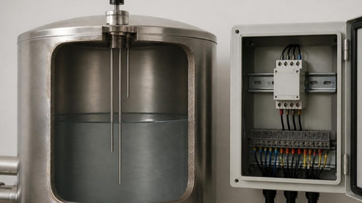
Set the sensitivity just above the resistance the liquid presents between the electrodes: high enough to switch reliably on the least conductive liquid you expect, low enough not to switch on foam, mist or a film on the holder. ABB's commissioning procedure for its older CM-ENN level relay, which has three switchable resistance ranges, in short:
From the CM-ENN section of ABB's legacy liquid level relay catalog pages (distributor copy).
For water, Lovato gives a starting point: "the sensitivity level is normally set to 6-8kΩ. For less conductive liquids, like rain water, the sensitivity can be adjusted up to 50kΩ" (Lovato LVM20). Endress+Hauser describes the sign of a setting that is too high: "If the probe is covered and the red LED flashes continuously, the sensitivity setting is too high." Finder suggests its high-sensitivity 5 to 450 kΩ types for ice bank control in refrigeration systems.
Relay sensitivity is a resistance between electrodes, in kΩ. Liquid tables usually give resistivity in kΩ·cm or conductivity in µS/cm. A table's kΩ·cm figure equals the relay's kΩ only when the electrodes form a cell constant of 1 cm⁻¹: METTLER explains that the reading "depends on the geometry of the measuring cell", the ratio of electrode distance to area. Use liquid tables as a guide for the first setting and adjust on the real tank. Make the final setting with the coldest, least conductive liquid the process will see: water conductivity "increases by 0.5 to 3 percent per degree Celsius" (USGS TM 9-A6.3), so a setting that only just trips on warm water can drop out on cold.
On any one relay, the allowed electrode cable gets shorter as the sensitivity setting goes up, because the cable's own capacitance starts to look like a wet electrode. METTLER describes the effect: "the capacitance of the cable between the electrodes and the measuring circuit may be more significant and should be minimized".
| Relay | Electrode voltage / current | Sensitivity | Max electrode cable | Delay |
|---|---|---|---|---|
| Finder 72.01 | 4 V AC / 0.2 mA | 5 to 150 kΩ (5 to 450 kΩ version) | 200 m (cable up to 100 nF/km) | 0.5 s or 7 s |
| ABB CM-ENS.2x | max 6 V AC / max 2 mA | 0.1 to 1000 kΩ, 4 ranges | 1000 m up to 10 kΩ, 100 m to 100 kΩ, 20 m to 1000 kΩ | no delay setting; measuring cycle 0.7 to 5 s by range |
| Schneider RM35LM33MW | ≤ 12 V / ≤ 1 mA | 0.25 to 5, 5 to 100, 50 to 1000 kΩ | 100 m; ≤ 4.7, 2.2, 1 nF | 0.1 to 5 s |
| Crouzet LN | max 24 V AC / max 1 mA | 5 to 100 kΩ | 100 m; max 10 nF | 0.3 s high, 0.5 s low |
| Carlo Gavazzi CLD1EA1CM24 | max 5 V AC / max 2 mA | 5 to 150 kΩ | 100 m; max 2.2 nF | 1 to 30 s on and off |
| Lovato LVM20 | 7.5 V AC / 0.4 mA max | 2.5 to 50 kΩ | 800 m at 2.5 kΩ, 150 m at 25 kΩ, 100 m at 50 kΩ | fixed, under 1 s |
Schneider data from a 2013 copy of its data sheet hosted by a distributor; all other cells from the makers' own documents linked in the first column.
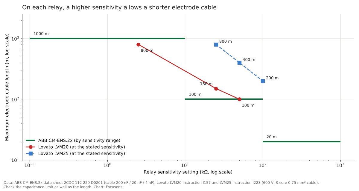
Check the capacitance limit as well as the metres. On a cable of 100 pF per metre, Finder's reference figure, Schneider's 1 nF high-sensitivity limit is reached at about 10 m and Carlo Gavazzi's 2.2 nF at about 22 m, both well short of the 100 m on the same sheets (our calculation). On the 200 pF/m implied by ABB's own figures (200 nF per 1000 m), the same limits are reached at about 5 m and 11 m (our calculation). Relays also differ from each other: Lovato's LVM25 instruction gives 800 m at 25 kΩ, 400 m at 50 kΩ and 200 m at 100 kΩ, where its LVM20 allows 150 m at 25 kΩ. The cable maker's pF/m figure decides which limit applies first.
| What the relay does | Installation or setting cause | Check at the relay or the fitting |
|---|---|---|
| Stays "wet", or will not release, with the electrodes dry | Sensitivity set above what the liquid needs; electrode cable too long or too capacitive for the range (section 8); moisture or a deposit across the holder; probe in the filling stream | Drop one sensitivity range; compare the cable's metres and nF with section 8; dry and reseal the fitting and conduit entry; move the probe out of the inflow |
| Does not switch with the electrodes covered | Sensitivity too low for the coldest or least conductive batch; scaled rods or tank wall; PTFE tape on the thread of a metal tank; reference terminal tied to panel ground | Raise the sensitivity one range; clean; use a conductive seal or a ground wire; keep the reference off panel ground |
| Switches repeatedly at one electrode | Single-electrode wiring with no MIN/MAX pair and no delay | Wire a MIN electrode, or set an on/off delay |
| Misbehaves only when a second relay runs | Unsynchronised supplies; an old-style Gems Warrick relay (Series 1 or 2) in the same tank as a current one | Use relays built to share a tank (E+H master and slave, below); do not mix old-style and current Gems Warrick relays, because the old style "sent a higher voltage out on the probes" (Gems) |
For liquid-side faults (liquid too pure, conductive foam, corrosion from DC drive) and the matching float-switch faults, see the failure table in our conductive level switch vs float switch guide.
Moisture is a common cause of false "wet" signals. Gems notes that "moisture can wick down electrical conduit lines and build up" in the probe fitting, and advises against filling the fitting with non-conductive silicone, which can trap it (Gems over-sensing troubleshooting). For relays sharing one tank, Endress+Hauser uses a master and slave arrangement on its Nivotester to prevent "a phase shift between the supply signals" (E+H Nivotester FTW325, distributor copy).
To test the relay without the tank, link the terminal used for single-level service to the reference terminal: on a Gems Warrick 16M that is H to G, and the relay should act as if the probe were wet (Gems bench test). Which terminal that is varies by maker: ABB connects only MAX, while Lovato's LVM20 shorts MAX to COM and switches on MIN (Lovato LVM20). On a two-point relay, link the lower and the upper terminal to the reference: the relay should switch. Remove the upper link: it should stay latched, and release only when the lower link comes off too. The latch step has to be watched with the relay powered, as in Gems' procedure, which reads the relay's LED and contacts after each link is removed; a relay that loses its supply loses the latched state (ABB's CM-ENS.2x bridges supply failures of only 20 ms). Fit the links with the supply off, then switch on and lift them with insulated test leads, after checking the relay's isolation statement (section 10); many of these relays are supplied at 110 to 240 V AC on terminals next to the electrode terminals.
Whether the electrodes are safe to touch depends on how the relay separates the electrode circuit from its supply and on what that supply is, and that varies by model. Endress+Hauser describes its Liquipoint T as "a closed, potential-free circuit between the probe rods and the electronics" and states that "there is absolutely no danger if the probe rods are touched during operation" (E+H TI00375F). Finder's 24 V DC types have "no electrical isolation between electrodes and supply voltage", so Finder says a SELV application needs a non-grounded SELV supply, and on a grounded (PELV) supply it requires "that no electrodes are grounded", to protect the relay "against harmful circulating currents"; its 24 V AC types have "an internal isolating transformer" giving reinforced isolation (Finder 72 series). Siemens marks its 24 V version of the 3UG4501 "no galvanic isolation from measuring circuit" (Siemens 3UG4501-1AA30, distributor copy). Check the isolation statement on the relay's data sheet; for hazardous areas, intrinsically safe versions exist, such as the E+H Nivotester FTW325 with an intrinsically safe [Ex ia] signal circuit (IEC 60079-11).
For oil, fuel, pure ethylene glycol or deionised water, a float switch does the job, because it responds to buoyancy rather than conductivity. Our conductive level switch vs float switch guide compares the two by liquid, with a conductivity table and the failure modes of each.
| Parameter | Typical value / note |
|---|---|
| Sensing medium | Conductive liquids, roughly 7.5 to 100 µS/cm or more, depending on the relay |
| Rod materials | 316L / 316Ti stainless steel, Hastelloy, titanium, tantalum, carbon fiber; PP, PTFE, FEP or PE insulation |
| Holder limits | about +60 to +180 °C ambient and up to 63 bar, depending on model |
| Mounting | Threaded holders, rod or suspended cable electrodes |
| Electrical data | See the summary table at the top and the relay comparison in section 8 |
Ranges compiled from the relay and electrode documents linked above, including the Lovato level controls brochure, the Pepperl+Fuchs HR-6 electrode and VEGA EL 3 specifications.
Focusens makes reed float level switches, not electrode probes. For liquids that do not conduct, see our guide to choosing between a conductive level switch and a float switch, and our float level switch range.
An electrode level sensor works by passing a small AC current through the liquid between electrodes. When conductive liquid covers a detecting electrode and the reference, the resistance between them falls below the relay's sensitivity and the relay switches. Each electrode marks one level.
Most electrode level sensors use AC to avoid electrolysis. Direct current would corrode the electrodes and decompose the liquid at their surface; alternating current largely prevents this, although ions still build up slightly at the electrodes.
You can use a metal tank wall as the reference electrode if the wall is clean, electrically connected to the relay, and the relay allows a grounded electrode: Finder's non-isolated 24 V DC types must not have a grounded electrode when they run from a grounded supply. A plastic tank needs a separate reference rod, longer than the others. Thread tape or scale on the wall can break the connection.
The data sheets compared here allow 20 m to 1000 m of electrode cable, depending on the relay and its sensitivity setting, and a relay's 1 nF limit can cut that to about 5 to 10 m on cable of 100 to 200 pF/m (our calculation). ABB's CM-ENS.2x allows 1000 m up to 10 kΩ but 20 m above 100 kΩ. Check the capacitance limit on the data sheet as well.
A conductivity sensor measures how well a liquid conducts, in µS/cm, to monitor water quality or concentration. A conductive level switch, also sold as a conductivity level switch, only uses the liquid's conductivity to tell whether liquid is present at an electrode.
Drafted with AI assistance from the documents linked on this page; reviewed by the Focusens Engineering Team on November 4, 2026. Electrode voltages, sensitivities, cable lengths and wiring logic come from the Finder, ABB, Schneider, Crouzet, Carlo Gavazzi, Lovato, Eaton, Siemens, Gems, Endress+Hauser and VEGA documents linked in each section. Figures marked "our calculation" are computed from those documents. The tank diagram is an illustration and the chart is drawn from the data sheets cited; no figure on this page is a Focusens measurement. Focusens does not make or sell electrode probes or level relays.
No.1 XiSan Road, Electromechanical Industry Park , High&New Tech.Zone. Hefei,Anhui,China
telefone : +86-551-69109668
Whatsapp : +86-13339100504
o email : info@focusens.com
Skype : melodyliu520






 +86-551-69109668