PTC thermistor for motor winding protection: wiring and selection
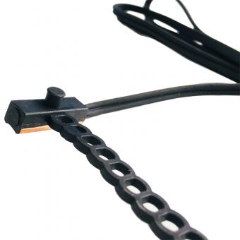
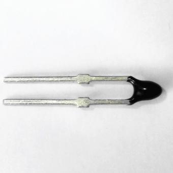
Sep 10, 2026Three PTC thermistors go into a three-phase motor, one per phase, embedded in the winding heads and wired in series to a protection relay. Below the rated temperature the string sits at a few hundred ohms.
When any one of the three passes its rated point, the string crosses about 4 kΩ and the relay drops the contactor.
The numbers in that paragraph are the whole design. This page gives them, explains why a series string triples every threshold, and covers how to choose the rated temperature against the motor's thermal class.
Published 10 September 2026. Reviewed by the Focusens technical department.
A thermal overload relay infers winding temperature from line current. That inference holds while the motor is cooled normally and fails in the cases that actually burn windings:
blocked ventilation, high ambient, a clogged filter, rapid start-stop duty, or a motor running at rated current in a hot room. Current looks normal. The winding does not.
An embedded PTC measures the winding itself, so none of those cases hide from it. It does not replace a current-based device, because it cannot see a locked rotor fast enough and it does not protect against short circuits. Standard practice is to run both.
A PT100 in the winding gives a continuous temperature reading instead of a threshold, which is what you want on a large machine with a monitoring system. The PTC is the cheaper last line: no scaling, no calibration, two states.
A switching PTC is specified by resistance at fixed offsets from its rated temperature, written TK. The relay is built around those offsets rather than around a temperature. MZ6 series values for rated points between 90 and 160 °C, TK tolerance ±5 °C:
| Measured at | Single element | Three in series |
|---|---|---|
| 25 °C | ≤100 Ω | ≤300 Ω |
| TK − 5 K | ≤550 Ω | ≤1650 Ω |
| TK + 5 K | ≥1330 Ω | ≥3990 Ω |
| TK + 15 K | ≥4 kΩ | ≥12 kΩ |
From the Focusens MZ6 series datasheet. Rated points of 60 to 85 °C and 165 to 190 °C use a different threshold set with a wider tolerance band, so read the row for the TK you are ordering.
Every value in the right column is exactly three times the left. That is the property the whole scheme depends on:
a relay whose trip point was set for a single element still reads a three-element string correctly, because the string scales linearly and only one element has to go high to carry the sum past the threshold.

Threshold values from the Focusens MZ6 datasheet. Only two wires leave the motor regardless of how many elements are in the string.
The 25 °C row is the row people test against, and it is the least informative one on the page.
Cold resistance is specified only as a maximum, ≤100 Ω for a single element and ≤300 Ω for a string. A healthy element and a marginal one both sit well under it.
Nothing about the value at 25 °C predicts whether the step will land where it should, because the step is a property of the ceramic's transition and the cold state is far away from it. Two consequences. A goods-inwards check at room temperature confirms continuity and nothing else.
And a bench test with a heat gun proves nothing unless it actually takes the element through TK, which for a 155 °C part means real heat under control, not a hairdryer.
The general procedure and the reading-interpretation table are in how to test a PTC thermistor with a multimeter.
TK is chosen against the motor's thermal class. Thermal classes are named by their temperature in degrees Celsius, so class 130 is the old class B, class 155 is F and class 180 is H.
Machine temperature-rise limits for each class are set in IEC 60034-1, and the requirements for built-in thermal protection of rotating machines are in IEC 60034-11.
The MZ6 series offers rated points at 60, 70, 80, 85, 90, 100, 110, 120, 130, 140, 150, 160, 165, 170, 180 and 190 °C, with TK to customer requirement.
Two rules govern the choice. The trip point has to sit at or below the limit for the insulation class, since the purpose is to act before the insulation is damaged.
And it has to sit above every temperature the winding legitimately reaches in normal duty at maximum permitted ambient, or the machine will trip on nothing.
The gap between those two figures is the whole working margin, and on a machine that runs hot in a hot room it can be narrow. Where the sensor sits matters as much as the number. A PTC bonded into the winding head reads close to the hotspot.
One mounted on the frame reads the frame and lags the winding by minutes, which on a blocked-cooling event is the difference between a trip and a rewind. Sensor placement is a machine-design decision, and TK should be chosen for the position the sensor will actually occupy.
The string is two wires from the motor terminal box to the relay, regardless of how many elements are inside. MZ6 assemblies are supplied as kits of two to six elements in series for machines that need more than one sensor per phase.
| Item | Value | Why it matters |
|---|---|---|
| Working voltage | ≤30 V DC | the relay supplies this; do not megger-test through the sensor circuit |
| Dielectric strength | AC 2.5 kV | insulation between the element and the winding it sits in |
| Response time | ≤5 s | how fast the element itself reacts once its own body reaches temperature |
| Max controlled temperature | 190 °C | above this the element is outside its specification |
| Cold resistance, string | ≤300 Ω for three | relays specify a maximum total cold resistance |
From the Focusens MZ6 series datasheet.
The voltage limit is the one that gets violated. A PTC sensor circuit is a low-voltage measurement circuit, and an insulation-resistance test at 500 V or 1000 V applied across it will destroy the elements.
Disconnect the sensor pair at the terminal box before any megger test on the machine, and check that the test procedure in your works instruction actually says so.
The other limit is total cold resistance. Relays specify a maximum they can distinguish from a trip, and a long sensor cable adds to the string. Where a machine sits far from its panel, confirm that cable resistance plus string resistance stays inside the relay's window.
Relays for this duty are built to IEC 60947-8, the standard covering control units for built-in thermal protection of rotating electrical machines. Many variable-speed drives include a PTC input to the same definition, which removes the separate relay.
The sensor and the relay are covered by different documents, and mixing them up produces specifications that cannot be met.
| Document | Covers |
|---|---|
| DIN VDE V 0898-1-401, formerly DIN 44081 and DIN 44082 | the sensor's resistance-temperature thresholds. MZ6 conforms |
| IEC 60738-1 | the international generic specification for PTC thermistors |
| IEC 60947-8 | the relay or control unit that reads the sensor |
| IEC 60034-11 | built-in thermal protection of the machine as a system |
| IEC 60034-1 | machine rating and the thermal class limits TK is chosen against |
The DIN standard behind the threshold values, including the colour coding used to identify rated temperature, is covered in the DIN 44081 and DIN 44082 guide.
Measure the string cold at the panel end, with the sensor pair disconnected from the relay, and confirm it is inside the relay's cold-resistance window with the cable included. Confirm the works instruction excludes the sensor pair from insulation testing.
Force a trip using the relay's own test function rather than by heating the motor, and confirm the contactor drops and the reset behaves as the application needs, because a self-resetting circuit on a machine that restarts unattended is a hazard rather than a convenience.
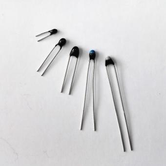
Then record which TK was fitted. A motor rewound three years later by someone who cannot tell a 130 °C element from a 155 °C one by looking is the reason the colour coding exists.
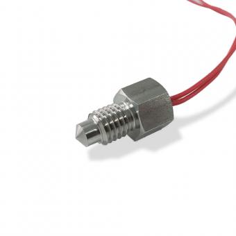
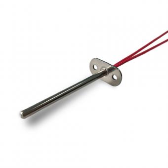
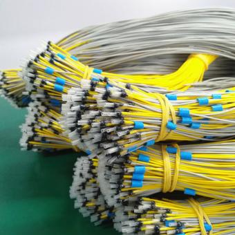
Focusens MZ6 assemblies are built as single, duplex, triple and sextuple kits to DIN VDE V 0898-1-401 with rated points from 60 to 190 °C.
A common configuration is the three-wire series 170 °C motor and machine protection sensor. The wider range sits under PTC thermistors, and the device families are compared in the PTC thermistor guide.
color:#11181D;font-family:Helvetica Neue , Arial, sans-serif;font-size:medium;white-space:normal;background:#FAF9F4;border:1px solid #DDD8CB;border-left:4px solid #0A6B3B;border-radius:4px;padding:16px 18px;margin:22px 0;line-height:1.75;This page covers the switching side. Where the winding carries a measuring element instead, and the drive is set for the wrong type, see KTY84 vs PT1000: what a drive reads with the wrong sensor.No.1 XiSan Road, Electromechanical Industry Park , High&New Tech.Zone. Hefei,Anhui,China
telefone : +86-551-69109668
Whatsapp : +86-13339100504
o email : info@focusens.com
Skype : melodyliu520






 +86-551-69109668