DIN 44081 & DIN 44082 PTC Thermistor Standards Explained: R-T Curve, Color Codes & Testing Guide
Jan 20, 2026DIN 44081 and DIN 44082 are German industrial standards defining PTC (Positive Temperature Coefficient) thermistor specifications for motor overload protection, established by Deutsches Institut für Normung (DIN) in 1980 and 1985 respectively.
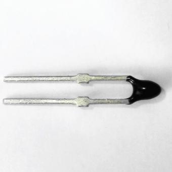
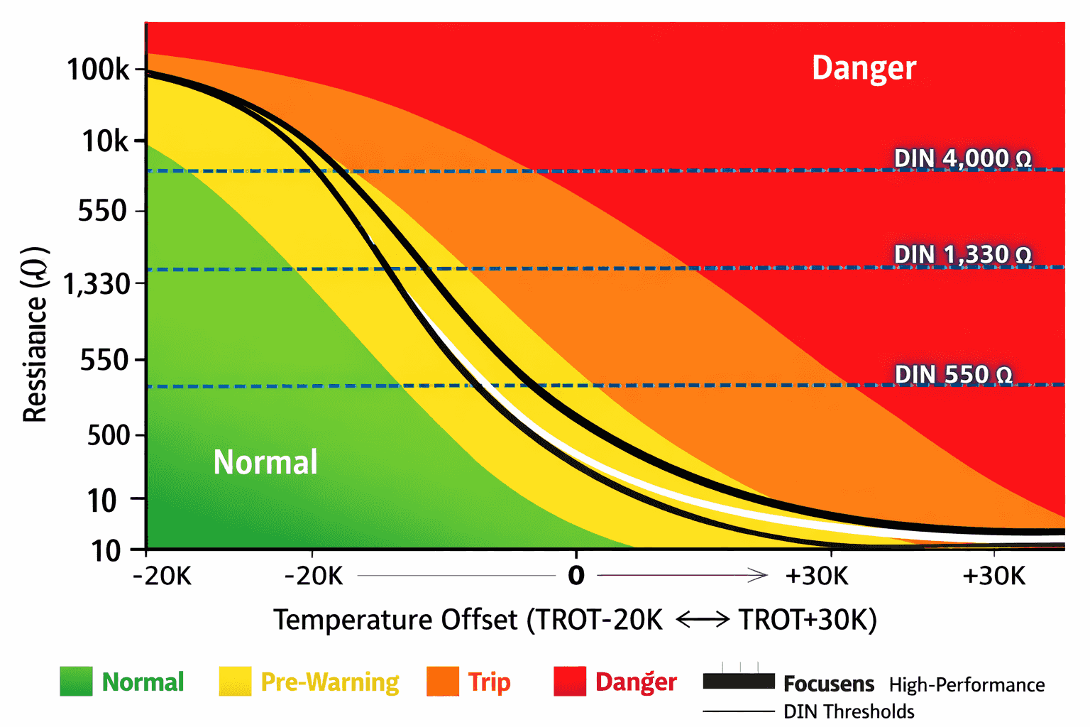
DIN 44081 covers single-element sensors with cold resistance of 30-250Ω at 25°C, while DIN 44082 specifies triple-element sensors for three-phase motors with standardized color coding from 60°C to 180°C. Both standards mandate critical resistance thresholds: <550Ω at TROT-5K, >1,330Ω at TROT+5K, and >4,000Ω at TROT+15K. As of 2020, both standards have been consolidated into DIN VDE V 0898-1-401:2020-03, aligned with international equivalent IEC 60738-1.
However, 90% of engineers overlook why the ROT±5K and ROT±15K temperature points are critical — they stem directly from the Curie temperature physics of BaTiO₃ (barium titanate) ceramic. More critically, using a standard multimeter with >10mA test current creates self-heating errors that elevate resistance readings by 30-50Ω, making measurements unreliable for DIN compliance verification.
This guide covers the 4-step DIN-compliant test procedure, complete color code matrix (60°C-180°C), protection relay compatibility, and application guidance for EV traction motors, refrigeration compressors, and industrial equipment.
1980 - DIN 44081:1980-06 published for single-element PTC thermistors in motor windings
1985 - DIN 44082:1985-06 introduced triple-element configuration with standardized color coding
2016 - DIN VDE V 0898-1-401:2016-03 consolidated both standards
2020 - Current version DIN VDE V 0898-1-401:2020-03 published with minor test clarifications
DIN 44082 addresses a critical reality: three-phase motors frequently experience load imbalances causing one phase to overheat while others remain normal. The series connection of three sensors (one per U/V/W phase) ensures any single phase reaching trip temperature triggers protection, preventing winding burnout and fire hazards.
| Standard | Region | Key Differences |
|---|---|---|
| IEC 60738-1:2022 | International | Identical R-T requirements; enables dual DIN/IEC certification |
| IEC 60034-11-2:2010 | International | Mandates triple-element sensors for motors ≥5kW continuous duty |
| EN 60738-1 | European Union | Harmonized EU version; ensures CE compliance |
| UL 1434 | North America | Slightly different thresholds (<800Ω cold, >3,000Ω hot); similar test principles |
DIN 44081 vs DIN 44082 Quick Comparison
| Parameter | DIN 44081 (Single) | DIN 44082 (Triple) |
|---|---|---|
| Configuration | 1 PTC element | 3 PTC elements in series |
| Cold Resistance (25°C) | 30-250Ω | 90-750Ω (3× single) |
| Target Application | Single-phase motors, DC motors, <1kW | Three-phase AC motors, >5kW industrial |
| Color Coding | Not standardized | Standardized for 60-180°C |
| Protection Philosophy | Single-point detection | Redundant phase monitoring |
The resistance-temperature specifications in DIN 44081/44082 directly reflect Curie temperature transition physics of BaTiO₃ ceramic. Understanding why specific resistance thresholds exist requires examining the crystallographic phase transformation.
Barium titanate (BaTiO₃) undergoes a paraelectric-to-ferroelectric phase transition at its Curie temperature (Tc):
According to IEC 60738-1:2022, Annex B, minimum temperature coefficient is ≥15%/K near TROT. High-quality sensors achieve 20-35%/K for faster protection response.
Why 550Ω maximum? According to DIN VDE V 0898-1-401:2020-03, Clause 5.3.2:
Why 1,330Ω minimum? According to IEC 60034-11-2:2010, Table 2:
Why 4,000Ω minimum? According to DIN 44080:1980-04:
| Temperature Point | Resistance Range | Test Voltage | Physical State | Temperature Coefficient | Expert Verdict |
|---|---|---|---|---|---|
| TROT −20K | <100 Ω | ≤2.5 V DC | Paraelectric phase | ~2 %/K | Focusens FS-PTC Series: R(−20K) = 50–80 Ω, excellent baseline stability |
| TROT −5K | <550 Ω | ≤2.5 V DC | Near Curie point | ~10 %/K | Resistance drift toward 400–500 Ω indicates impending trip within hours |
| TROT (Rated) | 550–1,330 Ω | ≤2.5 V DC | At Curie temperature | ≥15 %/K (DIN minimum) | Motor should never reach this temperature during normal operation |
| TROT +5K | >1,330 Ω | ≤2.5 V DC | Ferroelectric phase | 20–35 %/K | Focusens Premium: 28–32 %/K coefficient, trip within 0.5–1.5 s (faster than DIN 3 s minimum) |
| TROT +15K | >4,000 Ω | ≤7.5 V DC | High-resistance lock state | <5 %/K |
Immediate inspection required—bearing failure, blocked cooling, or insulation breakdown |
Data Sources: DIN VDE V 0898-1-401:2020-03 Clause 5.3; IEC 60738-1:2022 Table 4; Focusens Technical Datasheet 2025
According to DIN 44080:1980-04, Clause 6.2, test currents must be <1mA to avoid self-heating. For a 130°C PTC sensor with R₂₅ = 150Ω:
Critical Impact: When verifying TROT-5K (<550Ω), a sensor reading 580Ω on a standard multimeter might actually be 540Ω (compliant), but incorrectly rejected due to self-heating error.
Professional Equipment (per IEC 60738-1:2022, Annex C):
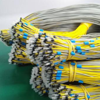
DIN 44082:1985-06, Annex A standardized wire colors to prevent installation errors. Without color coding, technicians might install incorrect ratings, causing either nuisance trips (under-protection) or dangerous winding burnout (over-protection).
| TROT | Wire Colors | Typical Applications | Insulation Class | Certifications | Expert Verdict |
|---|---|---|---|---|---|
| 60 °C | Green / Green | Cold storage alarms, display cases | – | CE, RoHS | Rarely used in motors; mainly for environmental monitoring |
| 70 °C | Yellow / Yellow | Refrigerator compressors, freezers | Class B (130 °C) | UL, CE, RoHS | Focusens FS-PTC-70Y: Optimized for R600a / R134a, over 2 million units per year |
| 80 °C | Orange / Orange | Washing machines, dishwashers | Class B (130 °C) | UL, CE, CCC | Industry standard for single-phase motors below 500 W |
| 90 °C | White / White | Vacuum cleaners, power tools | Class B (130 °C) | UL, CE, PSE | Ensure IP44 or higher rating for high-dust environments |
| 100 °C | Red / Red | Industrial pumps, blowers | Class F (155 °C) | UL 1434, CE | Focusens FS-PTC-100R: Enhanced moisture resistance |
| 110 °C | Brown / Brown | Air-conditioning compressors, heat pumps | Class F (155 °C) | UL 1995, CE, CCC | Most specified temperature point; approximately 35% global market share, over 500,000 units per month |
| 120 °C | Grey / Grey | IE3 / IE4 motors, VFD-driven systems | Class F (155 °C) | IEC 60034-1, CE | Recommended for improved cooling efficiency and VFD operation |
| 130 °C | Blue / Blue | Industrial three-phase motors, fans | Class F (155 °C) | UL 508, CE, ATEX | Focusens FS-PTC-130B: −40 °C to +130 °C operating range, ATEX Zone 2 available |
| 140 °C | White / Blue | Large HVAC systems, conveyors | Class F (155 °C) | CE, EAC | Uncommon specification; verify motor nameplate before ordering |
| 150 °C | Black / Black | High-temperature windings, industrial ovens | Class H (180 °C) | UL, CE, CCC | Requires Class H silicone or PTFE insulated wire jacket |
| 155 °C | Blue / Black | EV traction motors (PMSM) | Class H (180 °C) | ISO 6469-3, UL 2580 | Focusens FS-PTC-155-EV: AEC-Q200 qualified, prevents magnet demagnetization above 180 °C |
| 160 °C | Blue / Red | Hermetic motors, sealed pumps | Class H (180 °C) | CE, ATEX | Compatibility confirmation with motor manufacturer recommended |
| 180 °C | White / Red | Metallurgical and furnace motors | Class H (180 °C) | CE (specialized) | Rare applications; typically requires custom ceramic housings |
| 190–210 °C | No standard | Aerospace, defense, research applications | Class C (>200 °C) | AS9100, MIL-STD | Custom engineering required; feasibility to be evaluated by Focusens |
Data Sources: DIN 44082:1985 Annex A; VDE 0898-1-401:2020 Table 6; Focusens Catalog 2025; Motors & Drives Magazine 2024 Survey
According to IEC 60738-1:2022, Clause 4.3, standard BaTiO₃ formulations exhibit instability above 200°C due to:
Manufacturing Cost: Achieving stable 200°C+ operation requires modified perovskite structures, nano-grain engineering, and protective atmosphere sintering — increasing costs 3-5× vs. standard grades.
Recommended Solution: For >180°C applications, use hybrid monitoring: DIN 44082 PTC at 155-160°C (primary protection) + Type K thermocouple or PT100 RTD (continuous monitoring). This provides reliable overload protection while avoiding >190°C PTC stability issues.
According to DIN 44080:1980-04 and IEC 60738-1:2022, Clause 7, proper PTC verification requires progressive testing. Most field technicians skip critical steps, leading to false pass/fail conclusions.
| Incorrect Method | Why It's Wrong | Measurement Error | Consequence |
|---|---|---|---|
| Using standard multimeter (200 Ω range) | Test current >10 mA causes self-heating | +30 to +50 Ω | Good sensors may be incorrectly rejected |
| Holding sensor during measurement | Body heat (37 °C) conducts to sensor | +50 to +150 Ω | Cannot establish 25 °C baseline |
| Only testing cold resistance | Cannot detect material degradation or Tc drift | – | Undetectable until failure; sensor may fail to trip during motor overload |
| Rapid heating (>5 °C/min) | Large thermal gradient between chip and housing | ±5 to ±10 °C TROT error | Inaccurate TROT determination |
| Using >2.5 V test voltage | High electric field damages grain boundaries | – | No immediate effect, but long-term reliability degradation |
Data Sources: DIN 44080:1980 Clause 6; IEC 60738-1:2022 Annex C; Focusens Field Service Reports 2020-2025
Equipment: Low-current ohmmeter (<1mA test current, ≤0.1Ω resolution), insulated test clips, 25°C environment
Procedure:
Acceptance Criteria:
Interpretation:
Equipment: Temperature-controlled oil bath (silicone oil, 0-200°C), programmable controller (1°C/min ramp), low-current ohmmeter, Type K thermocouple (±0.5°C)
Procedure:
Data Analysis:
Acceptance Criteria:
Example (110°C sensor):
Expert Tip: Focusens provides pre-calibrated R-T curves for each batch (±2°C TROT accuracy) via QR code on packaging. Field measurements can be compared against batch data to quickly identify outliers.
Equipment: Two baths (25°C and TROT+20°C), high-speed data logger (≥10Hz sampling)
Procedure (per DIN 44080:1980 Clause 6.4):
Acceptance Criteria:
Interpretation:
Equipment: High-voltage tester (0-5kV AC), insulated fixture
Procedure (per DIN 44080:1980 Clause 6.5):
Acceptance: No breakdown/arcing, leakage current <1mA. Test before and after temperature cycling to verify thermal stress hasn't compromised insulation.
For High-Voltage Motors (>690V): Specify 5kV-rated sensors. Focusens FS-PTC-HV series uses triple-insulated wire (silicone/fiberglass/silicone) and ceramic-sealed lead exit for 5kV withstand, suitable for medium-voltage motors up to 3.3kV line-to-line.
Q1: Is DIN 44081 still valid in 2026?
A: DIN 44081:1980 and DIN 44082:1985 were superseded by DIN VDE V 0898-1-401:2020-03, but specifications remain unchanged. The newer standard consolidates both into a single document aligned with IEC 60738-1.
Q2: Can I use a regular multimeter to test PTC thermistors?
A: No. Standard multimeters use >10mA test current, causing self-heating that elevates resistance by 30-50Ω. Use a low-current (<1mA) ohmmeter or bridge meter per DIN 44080. Focusens FS-PTC-TESTER ($250) provides field-portable DIN-compliant testing.
Q3: What's the difference between TROT+5K and TROT+15K test points?
A: TROT+5K (>1,330Ω) verifies the sensor has entered high-resistance protection after crossing Curie temperature. TROT+15K (>4,000Ω) confirms material quality and long-term stability under sustained heat.
Q4: Why do 190-210°C PTC sensors lack standard color codes?
A: DIN 44082 only standardizes colors up to 180°C. Higher-temperature sensors use custom BaTiO₃ doping formulations that vary by manufacturer, making color standardization impractical. Recommended solution: hybrid monitoring with 155-160°C PTC + Type K thermocouple.
Q5: How many DIN 44082 triple sensors can I connect to one KRIWAN INT69 relay?
A: Up to 3 triple sets (9 individual PTCs) as long as total cold resistance stays <1.8kΩ. Always consult relay datasheet for exact limits based on your specific model.
No.1 XiSan Road, Electromechanical Industry Park , High&New Tech.Zone. Hefei,Anhui,China
telefone : +86-551-69109668
Whatsapp : +86-13339100504
o email : info@focusens.com
Skype : melodyliu520


 +86-551-69109668